Development of a principal process flow diagram for the synthesis of the TAS inhibitor against salt-plug formation in natural gas absorption purification units
УДК 665.61+66.097
Abstract
The article presents the synthesis technology of the TAS inhibitor designed to prevent salt-plug formation and mineral scale deposition in heat exchange equipment used in natural gas absorption purification systems. The formation of sparingly soluble calcium, magnesium, sulfate, and carbonate compounds in circulating cooling water is shown to reduce the heat transfer coefficient, increase hydraulic resistance and energy consumption, and shorten equipment service life. A continuous technological process for producing the inhibitor based on phthalic anhydride derivatives is proposed. The main synthesis stages, including phthalic anhydride chlorination, the reaction of the intermediate product with morpholine, and subsequent treatment with phosphoric acid to obtain the target compound, are described. The technological process incorporates reactors, separators, a scrubber, and a sedimentation centrifuge, ensuring efficient separation of reaction mixtures and recycling of unreacted raw materials. Particular attention is paid to the organization of the recycle system, which improves raw material utilization, reduces reagent consumption, and ensures uninterrupted operation of the process. The proposed technology provides higher product yield, lower energy consumption, and reduced operating costs associated with heat exchange equipment maintenance. The developed process flow scheme can be applied in the design of modern production facilities manufacturing scale inhibitors for the oil, gas, and chemical industries.
Аннотация
В статье рассмотрена технология синтеза ингибитора TAS, предназначенного для предотвращения образования солевых пробок и минеральных отложений в теплообменном оборудовании установок абсорбционной очистки природного газа. Показано, что образование труднорастворимых соединений кальция, магния, сульфатов и карбонатов в системах оборотного водоснабжения приводит к снижению коэффициента теплопередачи, увеличению гидравлического сопротивления, росту энергозатрат и сокращению срока службы оборудования. Предложена технологическая схема непрерывного получения ингибитора на основе производных фталевого ангидрида. Рассмотрены основные стадии синтеза, включающие хлорирование фталевого ангидрида, взаимодействие промежуточного продукта с морфолином и последующую обработку фосфорной кислотой с образованием целевого соединения. Описаны конструктивные особенности технологической схемы, включающей реакторы, сепараторы, скруббер и осадительную центрифугу, обеспечивающие эффективное разделение реакционных смесей и возврат непрореагировавших компонентов в процесс. Особое внимание уделено организации рециклинга сырья, позволяющего повысить степень его использования, снизить расход реагентов и обеспечить непрерывность производства. Показано, что предложенная технология способствует повышению выхода целевого продукта, сокращению энергетических затрат и снижению эксплуатационных расходов при эксплуатации теплообменного оборудования. Разработанная схема может быть использована при проектировании современных производств ингибиторов солеотложений для нефтегазовой и химической промышленности.
Keywords: TAS inhibitor; salt plugs; phthalic anhydride; chlorination; morpholine; phosphoric acid; AlCl₃ catalyst; heat exchanger; separator; sedimentation centrifuge.
Ключевые слова: Ингибитор TAS; солевые пробки; фталевый ангидрид; хлорирование; морфолин; фосфорная кислота; катализатор AlCl₃; теплообменный аппарат; сепаратор; осадительная центрифуга.
Introduction
The stable operation of heat exchange processes in natural gas absorption purification units is of great importance for the efficient removal of acidic components from natural gas. Calcium, magnesium, sulfate, and carbonate ions present in cooling water form sparingly soluble compounds under elevated-temperature conditions, resulting in the accumulation of salt deposits on equipment surfaces[1, 6].
Salt deposits reduce the heat transfer coefficient in heat exchangers and increase hydraulic resistance and energy consumption. Consequently, periodic cleaning of the equipment becomes necessary, which adversely affects production continuity and economic efficiency [2, 7].
The use of complexing and dispersing inhibitors is considered one of the most effective methods for preventing deposit formation. These inhibitors bind calcium and magnesium ions, restrict crystal growth, and reduce the adhesion of deposits to metal surfaces [9, 10].
The purpose of this study is to formulate an inhibitor composition against the formation of salt plugs in heat exchange equipment and to develop an efficient technological system for its synthesis [3, 8].
Materials and methods
The study was based on the analysis and development of a technological process for synthesizing the TAS inhibitor intended to prevent salt-plug formation in heat exchange equipment used in natural gas absorption purification systems. The research materials included published scientific literature on scale inhibition, process chemistry, and heat exchange equipment, as well as process data on the synthesis of phthalic anhydride derivatives. The methodology combined theoretical analysis of the reaction mechanism with process engineering design. Material and process flow analysis was applied to determine the sequence of chemical transformations, operating conditions, and recycle streams. The technological scheme was developed using principles of chemical process design, taking into account reaction kinetics, phase separation, heat removal, and continuous recycling of unreacted raw materials. The proposed synthesis route and equipment configuration were evaluated with respect to process continuity, product recovery efficiency, and rational utilization of reagents, providing the basis for an energy-efficient and economically viable production technology for the TAS inhibitor.
Results and discussion
Currently, particular attention is being paid to the production of competitive alternative products containing organic compounds based on phthalic derivatives in order to extend the service life of chemical industry equipment and ensure its operational stability.
At present, scientific research is being conducted to develop a new generation of auxiliary chemical reagents and improve their production technologies. Particular emphasis is placed on manufacturing competitive alternative products containing organic compounds based on phthalic derivatives that meet regulatory quality requirements, prevent the deterioration of chemical industry equipment, and ensure its stable operation[4 – 5].
The synthesis of the TAS inhibitor against salt-plug formation is based on a multistage catalytic process in which the inhibitor is produced using phthalic anhydride and chlorine as the main starting materials. It was established that the addition of a chlorine atom to phthalic anhydride results in the formation of a monochlorinated derivative of phthalic anhydride. The overall reaction can be represented as follows:
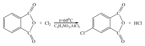
The process was carried out in a laboratory setup consisting of a specially equipped glass vessel (Fig. 1).
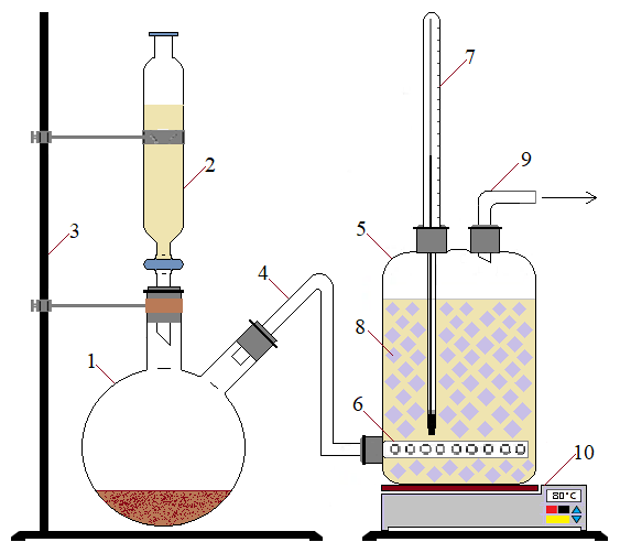
1 — Two-neck round-bottom flask; 2 — Separatory funnel; 3 — Separatory funnel; 4 — Gas inlet tube; 5 — Glass bottle; 6 — Gas distributor; 7 — Thermometer; 8 — Adapter; 9 — Gas outlet tube; 10 — Electric furnace.
Initially, 20 g of potassium permanganate was placed in a two-necked round-bottom flask (1). Then, 30 mL of hydrochloric acid was added to the separatory funnel (2) attached to the flask. The hydrochloric acid was added dropwise using the stopcock of the separatory funnel. At this stage, chlorine gas began to evolve. The generated chlorine gas was directed to the subsequent reaction stage through the gas delivery tube (4).
The generated chlorine gas was passed through a catalytic system consisting of phthalic anhydride, nitrobenzene, and AlCl3.
The liquid catalytic system was prepared as follows: 100 mL of nitrobenzene and 7.5 g of AlCl3 were placed in a 300 mL conical flask, and the mixture was stirred while being heated at 80 °C. After the AlCl3 had completely dissolved, 75 g of phthalic anhydride was added to the flask, and the mixture was stirred. Once a homogeneous system had formed, the mixture was cooled to 50 °C and transferred into the glass reaction vessel (5). The liquid in the vessel was then heated to 60 °C using an electric heater (10) to carry out the halogenation reaction.
The chlorine gas generated in the two-necked round-bottom flask (1) was continuously introduced through the gas delivery tube into the lower part of vessel (5) via the gas distributor (6). After 3 hours, the synthesis process was stopped, and the reaction mixture was cooled.
The functional groups present in the synthesized product were identified using infrared spectroscopic analysis (Fig. 2).
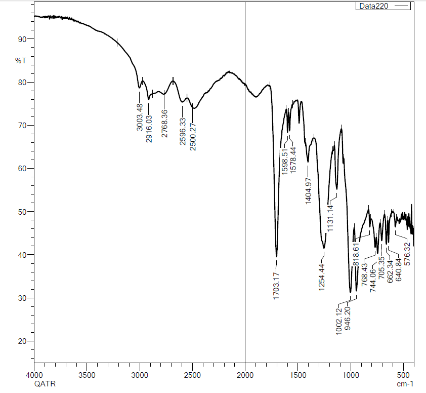
The absorption band at 1703.17 cm-¹ was assigned to the stretching vibrations of the carbonyl (C=O) group, while the band at 1254.44 cm-¹ corresponded to the stretching vibrations of the carboxyl group. In addition, the band at 3003.48 cm-¹ was attributed to the symmetric stretching vibrations of the aromatic C–H bonds. The absorption bands observed at 1254.44, 1131.14, and 1002.12 cm-¹ were assigned to the deformation and symmetric vibrations associated with the C–Cl bond in the aromatic ring.
However, because the characteristic carbonyl absorption bands of the anhydride group were not sufficiently resolved, the product structure was additionally investigated by gas chromatography–mass spectrometry (GC–MS). The structure of 5-chloroisobenzofuran-1,3-dione was evaluated based on the fragment ions observed in its mass spectrum (Fig. 3).
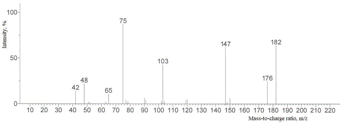
Analysis of the chromato-mass spectrum of the synthesized 5-chloroisobenzofuran-1,3-dione revealed the formation of ions corresponding to its molecular mass and to the masses of ionic fragments produced during fragmentation. The molecular ion peak of 5-chloroisobenzofuran-1,3-dione was observed at m/z 182, corresponding to its molecular mass.
At the intermediate stages of the process, 5-chloroisobenzofuran-1,3-dione and 5-morpholinoisobenzofuran-1,3-dione are formed. The obtained chlorinated derivative is subsequently reacted with morpholine to produce 5-morpholinoisobenzofuran-1,3-dione.
The reactions can be represented as follows:
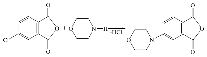
The synthesized 5-morpholinoisobenzofuran-1,3-dione was treated with H3PO4.
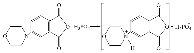
Phosphoric acid donates a proton (H+), resulting in protonation of the nitrogen atom and the formation of a positive charge. At the same time, the dihydrogen phosphate anion (H2PO4-) is formed. This is a protonation process occurring between phosphoric acid (H3PO4) and the nitrogen-containing compound acting as a base. In this reaction, phosphoric acid serves as the proton donor, while the nitrogen atom acts as the proton acceptor.
Since the densities of the products formed at the intermediate and final stages of the technological process are significantly higher than those of the initial substances, separator units are used to separate such reaction mixtures. These separators enable the efficient separation and recovery of the products.
At the same time, the unreacted initial substances that remain unchanged are returned to the reactors through a dedicated recycling system. This process allows the substances to be reused and increases the overall efficiency of the technological system. The recycled substances play an important role in maintaining the continuity and duration of the process.
Thus, the cyclic circulation of products and process materials within the system is ensured.
Process description
According to the proposed technology (Figure 4), chlorine, which is required for the formulation, is supplied at ambient temperature by compressor (12) at a flow rate of 15 m³/s through the gas distribution grid located in the lower section of reactor R-1 (1) to react with phthalic anhydride.
The operating temperature of reactor R-1 is maintained at 60 °C. The upper section of reactor R-1 is equipped with a droplet separator to prevent the liquid catalyst from being entrained and discharged together with the gaseous substances.
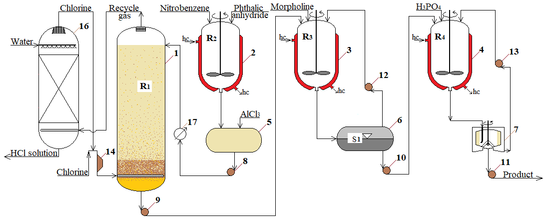
1, 2, 3, 4 – reactors; 5 – vessel; 6 – separator; 7 – sedimentation centrifuge; 8, 9, 10, 11, 12, 13 – pumps; 14 – compressor; 16 – scrubber; 17 – water cooler.
In this reactor, 5-chloroisobenzofuran-1,3-dione is formed. Nitrobenzene solvent and phthalic anhydride are fed into the jacketed reactor R-2 (2), operating at 103 °C, at flow rates of 2,3 kg/s and 9 kg/s, respectively. The reaction mixture in the jacketed reactor R-2 (2) is continuously and intensively stirred using a mechanical agitator.
AlCl3 catalyst is then added to the resulting solution from vessel (5) at a flow rate of 0,5 kg/s.
A measuring vessel is used to supply the subsequent continuous process stages with the product at the required flow rate. The resulting catalytic system is fed into the upper section of reactor R-1 (1) by pump (8) at a flow rate of 8 kg/s.
To ensure the continuous synthesis of 5-chloroisobenzofuran-1,3-dione, the raw materials are charged into reactor R-2 (2) in the quantities specified by the process regulations.
Since the chlorination reaction is reversible and exothermic, water-cooling systems are installed to increase the rate of the forward reaction. As the temperature decreases, the reaction equilibrium shifts toward the products. At temperatures below 60 °C, the reverse reaction is suppressed, resulting in a higher product yield.
The column-type design of reactor R-1 increases the number of contacts between the liquid phase, consisting of phthalic anhydride, nitrobenzene, and AlCl3, and the gas phase, consisting of chlorine, thereby improving the reaction yield. The liquid phase is introduced through the upper section of the column, flows through the distribution device, and is discharged from the lower section of the apparatus. Chlorine gas is introduced from the bottom of the apparatus.
The gas mixture consisting of unreacted chlorine and HCl formed during the reaction is discharged through a nozzle after passing through the droplet separator located in the upper section of reactor R-1. The droplet separator prevents the entrainment of the liquid phase into the gas stream.
The gas mixture consisting of chlorine that did not react with phthalic anhydride and HCl formed during the reaction is introduced into the lower section of scrubber column (16) in order to remove the HCl gas. The purified gas is discharged from the upper section of the scrubber and returned to the system as recycle gas.
Since the density of the resulting 5-chloroisobenzofuran-1,3-dione is higher than that of the initial substances, it accumulates in the bottom section of the R-1 reactor-column. This makes it possible to separate and recover the product in a purified form directly within the reactor.
The obtained 5-chloroisobenzofuran-1,3-dione is fed into the upper section of reactor R-3 (3) by pump (9). In reactor R-3 (3), 5-chloroisobenzofuran-1,3-dione reacts with morpholine to form 5-morpholinoisobenzofuran-1,3-dione.
The resulting reaction mixture, consisting of 5-chloroisobenzofuran-1,3-dione, morpholine, and 5-morpholinoisobenzofuran-1,3-dione, is discharged from the lower section of the reactor at a flow rate of 0.12 m³/s and a temperature of 25 °C and sent to separator S-1 (6) for phase separation.
The light phase, containing the unreacted raw materials, namely 5-chloroisobenzofuran-1,3-dione and morpholine, is withdrawn from the upper section of separator S-1 and recycled to reactor R-3 by pump (12).
The separated heavy phase, consisting of 5-morpholinoisobenzofuran-1,3-dione, is withdrawn from the lower section of the separator and fed into the upper section of reactor R-4 (4) by pump (10).
In reactor R-4 (4), 5-morpholinoisobenzofuran-1,3-dione reacts with concentrated phosphoric acid to form the TAS inhibitor. The operating temperature of reactor R-4 (4) is maintained at 25–30 °C.
The resulting reaction mixture, consisting of 5-morpholinoisobenzofuran-1,3-dione, phosphoric acid, and the TAS inhibitor, is discharged from the lower section of the reactor under specified process conditions at a flow rate of 0.17 m³/s and sent for separation. This process is carried out at a temperature of 25 °C, after which the reaction mixture is transferred to the sedimentation centrifuge (7).
The reaction products in the form of a suspension from reactor R-4 are fed into the upper section of the sedimentation centrifuge drum. As the drum rotates, centrifugal force is generated. Under the action of this force, the denser solid product settles and accumulates on the inner working surface of the drum.
The lower-density liquid phase, containing the raw materials that remained chemically unchanged in reactor R-4, namely 5-morpholinoisobenzofuran-1,3-dione and phosphoric acid, accumulates near the axis of rotation. The resulting centrate is then returned to reactor R-4 by pump (13) for further processing.
The physical properties of the synthesized TAS inhibitor for preventing salt plug formation were analyzed (Table 1).
Table 1.
Physical properties of the TAS inhibitor
| № | Property | Value |
|---|---|---|
| 1 | Appearance | Crystalline powder |
| 2 | Color | Light yellow |
| 3 | Solubility in water | Good; hygroscopic |
| 4 | Solubility in organic solvents | Limited |
| 5 | Decomposition temperature | 187.8 °C |
| 6 | Density | 1.3 g/cm³ |
| 7 | Molecular weight | 331 |
According to the analysis results, it was established that the physical properties of the substance are suitable for its application in the technological system.
The thermal stability of the TAS inhibitor was analyzed using the DTA method, which is one of the modern analytical techniques, and conclusions were drawn based on the results. The thermal stability of the synthesized substance is shown in the following figure (Fig. 5)
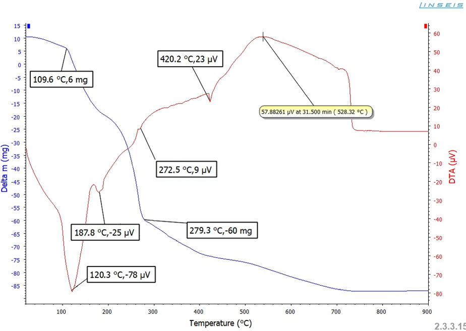
According to the analysis results, the decomposition temperature of the synthesized TAS inhibitor against salt plug formation was determined to be 187.8 °C.
The efficiency of the synthesized TAS inhibitor against salt plug formation was evaluated in accordance with GOST 9.905–82 using synthetic water with a total hardness of 8 mmol/L at 90 °C for 5 hours. The test results showed that the mass of the precipitate decreased significantly as the inhibitor concentration increased. At a concentration of 100 mg/L, the precipitate mass decreased from 118 mg to 9 mg, corresponding to an inhibition efficiency of 92.4 % (Table 2). According to the GOST criteria, this value indicates a high level of resistance to salt plug formation. The synthetic water was prepared by adding 0.68 g of CaCl2·2H2O, 0.64 g of MgCl2·6H2O, and 0.50 g of NaHCO3 to 1 L of distilled water.
Table 2.
Dependence of the efficiency of the TAS inhibitor against salt plug formation on its concentration
| № | Inhibitor concentration (mg/L) | Precipitate mass (m), mg | Efficiency (η), % |
|---|---|---|---|
| 1 | 0 | 118 | - |
| 2 | 10 | 74 | 37.3 % |
| 3 | 25 | 52 | 55.9 % |
| 4 | 50 | 27 | 77.1 % |
| 5 | 100 | 9 | 92.4 % |
The inhibitor suppresses the growth of CaCO3 and Mg(OH)2 crystals and effectively prevents salt plug formation in heat-exchange equipment.
Conclusion
The proposed technology for the synthesis of the TAS inhibitor provides an effective approach to producing a reagent for preventing salt-plug formation in heat exchange equipment used in natural gas purification systems. The developed process flow scheme ensures continuous operation through the recycling of unreacted raw materials, efficient phase separation, and the use of optimized operating conditions at each reaction stage. The application of reactor, separator, scrubber, and centrifuge units improves product recovery while reducing reagent losses and energy consumption. The proposed technological solution can contribute to enhancing the reliability of heat exchange equipment, extending its service life, reducing maintenance downtime, and improving the overall economic efficiency of industrial gas treatment processes.
References